FIFA LED stadium light smart system supplier in Bolivia


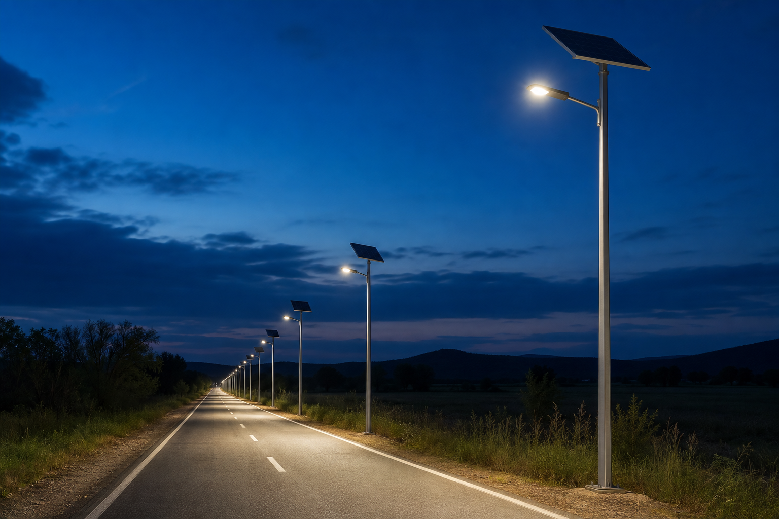
Quick Answer: A rural-road solar street light should be sized from the required lighting result and the worst relevant solar month—not from advertised lamp wattage alone. Define the road geometry, pole arrangement, nightly power schedule, local solar resource, autonomy requirement, battery operating limits, and environmental conditions. Then verify the optics with a model-specific photometric file and verify the energy balance with documented assumptions.
Rural projects often have limited grid access and long maintenance routes. An undersized battery or poorly selected distribution can therefore create dark sections, early dimming, and repeated service visits. The following method gives EPC buyers, municipalities, and distributors a practical way to prepare a solar street lighting RFQ without pretending that one configuration fits every road.
Start with a scaled road drawing or a clear dimensioned sketch. Record the carriageway width, number of lanes, shoulders, curves, intersections, pedestrian areas, nearby homes, proposed pole locations, mounting restrictions, and any obstacles that can shade the solar panel. The responsible road authority should define the target lighting class and acceptance method.
For the energy model, record the project coordinates, monthly solar resource, seasonal temperature, dust or snow exposure, required operating hours, dimming schedule, and requested autonomy. The European Commission’s PVGIS user manual explains how location-based solar radiation and hourly data can be obtained. NREL’s PVWatts calculator is another useful PV production reference, although an off-grid lighting design still needs a project-specific battery and control model.
| Input group | Minimum information | Design decision affected |
|---|---|---|
| Road geometry | Width, lanes, curves, intersections, shoulders | Optics, pole position, spacing |
| Lighting requirement | Target criteria, measurement area, acceptance method | Luminaire output and photometric layout |
| Solar resource | Coordinates, monthly irradiation, shading, panel orientation | Panel size and charging margin |
| Operating profile | Full-power hours, dimming periods, sensor logic | Daily energy demand |
| Environment | Temperature, dust, corrosion, wind, flooding risk | Battery margin, materials, maintenance plan |
Pole height affects the illuminated footprint, glare seen by road users, structural loading, and maintenance access. Spacing affects uniformity and the risk of dark zones. These two values must be selected together with the luminaire’s optical distribution, tilt, setback, overhang, and lumen output.
Do not approve spacing from a catalogue beam-angle label. Request the exact IES or LDT photometric file for the quoted model and run a calculation using the real road section. Check the required average or maintained lighting value, uniformity, glare criterion, and boundary conditions specified by the project authority. The applicable road-lighting rules differ by country and tender. IEC 60598-2-3 addresses particular product requirements for road and street lighting luminaires, but it does not replace the project’s road-lighting design criteria.
Use a concept layout only to compare alternatives. Final spacing should be confirmed by the approved simulation and, when required, by on-site measurement after installation. For broader road-project selection factors, see the solar street light highway project guide.
Convert the operating schedule into watt-hours rather than using the luminaire’s maximum power for the entire night. For each time block, multiply operating power by hours, then add the blocks:
Daily load energy (Wh) = Σ operating power (W) × operating time (h)
If a 30 W luminaire operates for five hours at full power and seven hours at 50% power, the illustrative load is:
(30 × 5) + (15 × 7) = 255 Wh per night
This is an example, not a recommended rural-road wattage or schedule. The real value must come from the approved optical design and control profile. Include controller consumption and other auxiliary loads where applicable.
Battery capacity must cover the design load while respecting allowable depth of discharge and allowing for temperature, conversion losses, and aging. A transparent preliminary equation is:
Nominal battery energy = adjusted daily load × autonomy days ÷ allowable discharge fraction ÷ environmental and aging factor
| Illustrative step | Assumption | Result |
|---|---|---|
| Nightly load | 30 W × 5 h plus 15 W × 7 h | 255 Wh |
| Allow for system losses | 255 Wh ÷ 0.85 | 300 Wh adjusted load |
| Three-day autonomy | 300 Wh × 3 | 900 Wh usable reserve |
| Preliminary nominal battery | 900 ÷ 0.80 ÷ 0.85 | About 1,324 Wh |
The 80% discharge fraction, 85% system factors, and three autonomy days are illustrative assumptions only. Battery chemistry, BMS limits, local temperature, reliability target, supplier data, and procurement rules determine the actual factors. Ask the supplier to state every assumption and distinguish nominal watt-hours from usable energy.
Annual average sunshine can hide the weakest charging season. Use the relevant monthly or hourly solar resource for the project coordinates, consider panel tilt and orientation, and account for module temperature, wiring, controller efficiency, dust, shading, and other losses.
A simplified screening equation is:
PV power (W) = adjusted daily load (Wh) ÷ design peak-sun-hours ÷ charging derating factor
Using the illustrative 300 Wh adjusted load, four equivalent peak-sun-hours, and a 0.75 derating factor gives 300 ÷ 4 ÷ 0.75 = 100 W. This is only a preliminary check. The final design must test seasonal energy balance, consecutive poor-weather conditions, recovery charging after deep discharge, panel soiling, and any restrictions on the charging window.
Dimming can reduce battery and panel size, but the schedule must still meet the authority’s lighting requirements. Define astronomical timing, fixed-time dimming, motion sensing, low-voltage protection, recovery behavior, and whether the controller stores operational data. Avoid unspecified “smart mode” descriptions.
For remote roads, design for safe access to the battery, controller, panel, luminaire, and fasteners. Confirm replacement procedures, spare parts, cleaning intervals, vegetation control, corrosion inspection, and fault diagnosis. Buyers comparing suppliers can use the solar street light manufacturer audit checklist to verify component traceability and quality records.
| RFQ item | Required submission | Buyer check |
|---|---|---|
| Road design | Scaled layout, pole positions, photometric calculation, IES/LDT file | Criteria and geometry match the tender |
| Energy model | Hourly load, solar data, losses, autonomy, recovery calculation | Worst relevant season is assessed |
| Battery and PV | Models, ratings, operating limits, traceability, test evidence | Quoted parts match the calculation |
| Mechanical system | Pole, bracket, foundation, wind and corrosion inputs | Local structural approval is defined |
| Service plan | Warranty process, spares, access method, maintenance schedule | Remote-road response is practical |
Review complete solar street light systems only after the project inputs are defined. This prevents a product catalogue from replacing the engineering brief.
There is no universal height. Select it with the road width, pole setback, required lighting criteria, luminaire distribution, glare control, structural conditions, and maintenance method, then verify it photometrically.
Spacing must come from the exact photometric file and road model. A spacing-to-height shortcut may help create a concept, but it cannot verify uniformity, glare, curves, intersections, or the required maintained result.
Base autonomy on local weather risk, road importance, acceptable dimming, maintenance response, battery limits, and procurement requirements. More days increase battery and charging requirements.
No. Battery sizing requires the complete hourly power schedule, controller consumption, system losses, usable discharge limit, autonomy, temperature, and aging assumptions.
Not by itself. Check the design month and poor-weather sequence relevant to the project, because annual averages can conceal weak seasonal charging conditions.
Request the layout, photometric calculation, model-specific photometric file, energy balance, battery and panel data, controller schedule, drawings, quality plan, applicable compliance documents, warranty process, and spare-parts proposal.
Need a project-specific rural road configuration?
Send the road width, pole layout, project coordinates, operating hours, autonomy target, quantity, and required lighting criteria. Request a Rural Road Solar Sizing Proposal.
Author 2024-08-06
LED technology itself is not automatically harmful to children’s eyes. This guide explains the differences between permanent eye damage, temporary visual discomfort and sleep disruption, while showing...
Author 2026-07-29
All-in-one and split solar street lights each offer different advantages. This guide compares their system structure, installation, solar panel flexibility, battery capacity, maintenance, cost, and su...