FIFA LED stadium light smart system supplier in Bolivia


Quick Answer
A reliable LED stadium lighting design starts with the venue dimensions, use level, camera directions, pole positions, target illuminance, uniformity and glare limits. Fixture wattage alone cannot determine the result. A point-by-point photometric model should verify horizontal and vertical illuminance, aiming angles, spill light and maintained performance before equipment is ordered.
Buyers and contractors need a clear project brief—not simply “the brightest floodlight.” The same fixture can produce different results when pole height, setback, beam angle and aiming change. This guide explains what to define before requesting a DIALux calculation or comparing LED sports lighting systems.
| Design input | Why it matters | Buyer information |
|---|---|---|
| Playing area | Controls the calculation grid | Dimensions, orientation and safety zones |
| Use level | Sets illuminance and broadcast needs | Training, match or televised event |
| Pole geometry | Changes beam choice and glare | Quantity, height, setback and load limits |
| Camera plan | Determines vertical illuminance | Camera directions and frame-rate needs |
| Environment | Affects wind, corrosion and spill light | Wind zone, temperature and neighbours |
Provide a CAD drawing or a dimensioned plan showing the pitch, run-off areas, stands, roofs, scoreboards, poles and nearby boundaries. For retrofits, include existing pole heights, bracket capacity, circuit arrangement and photographs from each pole position.
Also define the venue use. Players mainly need comfortable horizontal illumination and good visibility of the ball and other players. Cameras require vertical illuminance from several directions, good modelling of faces and uniforms, controlled flicker and consistent colour.
Sport, playing-area dimensions and competition level
Target horizontal and vertical illuminance
Uniformity ratios and glare limit
Pole positions, heights, setbacks and load limits
Voltage, control method and required lighting scenes
Environmental, spill-light and commissioning requirements
There is no universal lux value for every stadium. Requirements depend on the sport, governing body, competition category, camera plan and local regulations. The following current UEFA football-stadium values illustrate how requirements increase with venue category; they should not be copied automatically to other sports.
| UEFA category | Average horizontal | Average vertical | Horizontal uniformity |
|---|---|---|---|
| 1 | At least 350 lux, or broadcaster requirement | Project requirement | Confirm in project brief |
| 2 | 800 lux | 350 lux each reference plane | U1h > 0.4; U2h > 0.6 |
| 3 | 1,200 lux | 700 lux each reference plane | U1h > 0.4; U2h > 0.6 |
| 4 | 1,400 lux | 1,000 lux each reference plane | U1h > 0.5; U2h > 0.7 |
Reference: UEFA Stadium Infrastructure Regulations, Article 16, effective 1 June 2025. Confirm the latest competition and local requirements for each project.
Design values should include a justified maintenance factor. The objective is maintained performance after normal lumen depreciation and dirt accumulation—not only an attractive “day one” calculation.
Average lux alone is incomplete. UEFA defines U1 as minimum illuminance divided by maximum illuminance and U2 as minimum divided by average. Higher ratios indicate a more even result. Its official uniformity guidance notes that measured results can be lower than calculated values, so a design should not merely touch the minimum threshold.
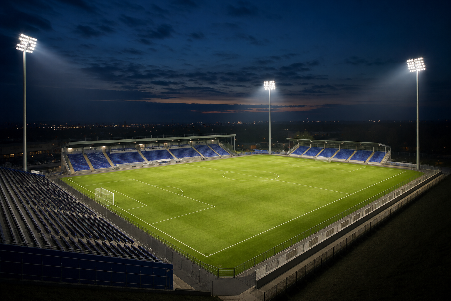
Glare depends on luminaire position, aiming direction, intensity at high angles and player sightlines. Narrow beams may be needed for long throws, but poor aiming can create uncomfortable high-intensity sources. Wide beams may help near-field coverage but increase spill light when uncontrolled.
Broadcast projects must also define colour rendering, correlated colour temperature and flicker performance. A “flicker-free” claim should be checked against the driver configuration, dimming scene and camera frame rate.
Higher mounting positions can improve coverage and vertical aiming, but increase throw distance and structural demand. Lower poles shorten the throw but can place intense light closer to player sightlines. A project may combine narrow beams for distant zones, medium beams for central coverage and wider distributions for near areas.
FIFA recommends assessing mast location, lighting equipment, aiming angles and beams together, while controlling glare and unwanted spill. See the official FIFA stadium technical guidance.
A lumen-method calculation is useful for early budgeting but cannot replace point-by-point simulation:
Quantity = (target lux × area) ÷ (fixture lumens × utilization factor × maintenance factor)
Example: a 105 m × 68 m pitch, 500-lux planning target, 160,000-lumen floodlight, 0.45 preliminary utilization factor and 0.90 maintenance factor:
Area: 7,140 m²
Required lumens on the plane: 500 × 7,140 = 3,570,000 lm
Estimated maintained output delivered per fixture: 160,000 × 0.45 × 0.90 = 64,800 lm
Preliminary quantity: 3,570,000 ÷ 64,800 = 55.1, rounded to 56 fixtures
The nominal 160,000-lumen input matches the published output of Hishine’s 1000W LED stadium lights. This is not a quotation or final design. Quantity can change after checking vertical illuminance, uniformity, glare, pole geometry, obstructions and IES files.
Selecting by wattage only: power does not describe beam distribution or delivered illuminance.
Checking average lux only: uniformity, vertical light and glare may still fail.
Ignoring structural limits: verify wind area, brackets and cable capacity first.
Using one beam everywhere: near, middle and far zones often need different distributions.
Omitting maintenance: a design that barely passes initially may fail in service.
Ordering before review: lock pole geometry and IES data before procurement.
Dimensioned plan, pole coordinates, heights and setbacks
Sport, venue level and applicable standard
Illuminance, uniformity, glare and broadcast requirements
Voltage, controls, operating scenes and maximum load
Wind, temperature, corrosion and spill-light constraints
Required DIALux report, IES files, aiming schedule and bill of quantities
Commissioning grid, measurement method and responsibility for aiming
Compare quotations only when suppliers use the same inputs. Results are not comparable when one proposal uses initial lumens and another uses maintained values, or when they assume different pole layouts.
It may suit some non-broadcast projects, but it is not universal. Confirm the competition authority, venue category, camera plan and local standard.
Both. Average lux describes the overall level; uniformity shows how evenly it is distributed and whether dark zones remain.
Only for an early estimate. Final quantity requires IES data, pole geometry, aiming, vertical planes, glare and spill-light checks.
No. It may improve coverage but increases throw distance and structural demand. The optimum height depends on the complete geometry.
It helps cameras capture players, the ball and facial detail from relevant directions, especially during televised events.
It should identify inputs, grid, luminaires, poles, aiming, maintenance factor, horizontal and vertical results, uniformity, electrical load and assumptions.
Need a project-specific stadium lighting design?
Send the field dimensions, pole layout, target level and electrical requirements for an initial project review.
Author 2024-08-06
LED technology itself is not automatically harmful to children’s eyes. This guide explains the differences between permanent eye damage, temporary visual discomfort and sleep disruption, while showing...
Author 2026-07-29
All-in-one and split solar street lights each offer different advantages. This guide compares their system structure, installation, solar panel flexibility, battery capacity, maintenance, cost, and su...