FIFA LED stadium light smart system supplier in Bolivia


Quick Answer: High mast lighting design must coordinate pole height, mast spacing, beam distributions, aiming, structural wind loads and maintenance access. The tallest pole or highest-wattage floodlight is not automatically the best solution. Start with a scaled site plan and performance criteria, complete a model-specific photometric calculation, and have a qualified structural engineer approve the mast, headframe, foundation and wind-load design.
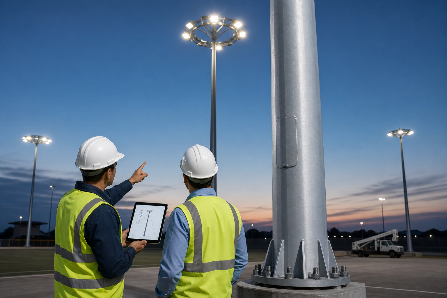
High mast systems illuminate large sports fields, interchanges, ports, airports and industrial yards while keeping the ground relatively clear. Lighting, structure, electrical distribution and maintenance are connected: changing the fixture arrangement or pole location affects structural and photometric performance.
This guide provides a practical high mast lighting design framework without inventing a universal pole height, fixture count or wind rating.
Begin with a scaled drawing and an approved project brief. The U.S. Federal Highway Administration describes high-mast lighting generally as a group of luminaires mounted at a height of 20 m or more, but the correct project height depends on geometry, performance and local engineering requirements.
| Input | Information Required | Design Effect |
|---|---|---|
| Illuminated area | Dimensions, boundaries, levels and obstructions | Controls pole positions, throw distances and calculation grids. |
| Application | Sport, port, interchange, apron, parking or industrial yard | Changes visual tasks and applicable criteria. |
| Performance | Maintained illuminance, uniformity, vertical light, glare and spill limits | Defines optics, aiming and quantity. |
| Operating scenes | Training, competition, working, security and curfew | Defines controls and annual energy. |
| Site conditions | Wind, corrosion, temperature, soil, access and nearby receptors | Changes structure, protection and maintenance strategy. |
Use the DIALux sports lighting project-data guide to prepare drawings, pole information, criteria and boundary inputs before requesting a proposal.
Higher mounting can improve coverage and create smoother aiming geometry, but it also increases structural demand, optical throw and maintenance complexity. Lower poles may reduce some structural scope but can require more locations and increase direct luminaire visibility.
Evaluate candidate layouts by asking:
Can each critical zone receive light from suitable directions?
Are poles outside safety clearances and operational routes?
Can the optics reach the far zone without excessive tilt or spill?
Do stands, roofs, cranes, trees or stored materials block light?
Can maintenance vehicles reach the base without closing the facility?
Are foundations clear of utilities, drainage and restricted soil zones?
Compare candidate heights using the same targets, grid and maintenance factor.
A high mast headframe normally needs more than one optical distribution. Narrow beams can serve distant zones; medium or asymmetric distributions can cover intermediate and near zones. The exact IES file, not a beam-angle label, determines the intensity pattern.
| Optical Task | Potential Approach | Risk to Check |
|---|---|---|
| Long throw | Narrow, controlled distribution | Hotspots, glare and aiming sensitivity. |
| Intermediate zone | Medium distribution | Dark transitions between beams. |
| Near zone | Wide or asymmetric distribution | Overlighting and light behind the mast. |
| Boundary control | Asymmetric optic, shielding or revised aiming | Spill light and high-intensity rays leaving the site. |
Consider a hypothetical mast with a 30 m mounting height and a far calculation point 45 m away horizontally. The straight-line optical throw is:
Throw distance = √(30² + 45²) ≈ 54.1 m
This geometry does not select the optic by itself. The designer still needs the target grid, luminaire intensity distribution, aiming angle, maintenance factor and glare/spill constraints. Review available LED sports and high mast lighting systems before assigning model-specific IES files.
More luminaires can provide more aiming points, but they also add weight, projected wind area, circuits and maintenance items. Fewer high-output luminaires may simplify the headframe but create larger steps of light and less aiming flexibility.
The returned calculation should identify each fixture by pole, model, wattage, optic, tilt and aiming point. Ask for horizontal and vertical results, uniformity, glare or spill checks, isolines and false-color views. The 1000W versus 1500W stadium-light comparison explains why total system performance matters more than a single wattage.
The lighting designer can provide fixture weight, dimensions, bracket drawing and effective projected area. A structural engineer must use the locally adopted code, site wind data, exposure, importance or risk category, topography, dynamic behavior, ice where applicable, and complete mast/headframe configuration.
ASCE/SEI 7-22 covers wind and other environmental loads for buildings and other structures in jurisdictions that adopt it. It is not a universal substitute for the project’s local code.
| Structural RFQ Item | What to Confirm |
|---|---|
| Luminaire assembly | Quantity, weight, projected area, centre of gravity and bracket details. |
| Headframe | Geometry, attachment, cable routing, lowering mechanism and spare positions. |
| Mast | Material, sections, welds, slip joints, access door and corrosion protection. |
| Base and foundation | Base plate, anchor bolts, grout, concrete, reinforcement and geotechnical data. |
| Environmental loads | Design wind, exposure, topography, ice, temperature and corrosion category. |
| Dynamic response | Wind-induced vibration, fatigue-sensitive details and required mitigation. |
FHWA research notes that flexible high-mast poles can experience wind-induced vibration and fatigue at welded details. A claimed “wind resistance level” on a product page is not a structural approval for the installed system.
Choose the maintenance concept while the layout is still flexible. Options may include a lowering headframe, fixed platform, mobile elevating work platform or other approved access method. The correct choice depends on mast height, site access, traffic or facility closures, technician safety, local regulations and available equipment.
Define how drivers, LED modules, surge devices and cables can be serviced.
Provide safe isolation, lockout and control procedures.
Protect lowering cables, winches and connectors from corrosion and contamination.
Confirm the storage and replacement policy for critical spare parts.
Include cleaning, aiming verification and post-storm inspections.
Inspection begins at installation. Record anchor-bolt condition, torque or tension procedure, grout, mast sections, welds, slip joints, headframe, wiring and corrosion protection. Keep drawings, material records and photographs linked to a unique mast ID.
The FHWA Ancillary Structures Inspection Reference Manual discusses high-mast tower inspection, including the use of multiple viewing positions and additional methods where defects are suspected.
Lighting commissioning should verify fixture model and optic, mounting orientation, aiming, control scenes and field measurements. Compare measured results with the approved maintained-design assumptions and document any correction.
Scaled site plan, boundaries, levels and obstructions.
Application, performance criteria, grid and maintenance factor.
Candidate mast locations, heights and access constraints.
Model-specific datasheets, IES files, weight and projected area.
Photometric report, pole schedule and fixture-by-fixture aiming table.
Local structural code, wind/ice/site data and geotechnical information.
Headframe, lowering/access, electrical and control requirements.
Installation, commissioning, inspection, spares and warranty responsibilities.
No. Greater height can improve coverage but also increases throw, structural demand and maintenance complexity. Compare complete layouts.
Usually the calculation should test a beam mix. Near, intermediate and far zones often require different intensity distributions.
A qualified structural engineer using the locally adopted code and complete installed configuration should approve the mast, headframe and foundation.
Only after structural, foundation, corrosion, fatigue and electrical review confirms their suitability for the new fixtures and site conditions.
Request the exact model, IES file, input data, weight, dimensions, projected area, bracket drawing, driver, surge and ambient-temperature information.
Verify structural and electrical installation records, fixture models and optics, aiming, control scenes, field measurements and a documented inspection baseline.
Send Hishine the scaled plan, performance criteria, candidate mast data, site conditions and structural design basis. The lighting team can prepare a model-specific photometric proposal for structural review.
Author 2024-08-06
LED technology itself is not automatically harmful to children’s eyes. This guide explains the differences between permanent eye damage, temporary visual discomfort and sleep disruption, while showing...
Author 2026-07-29
All-in-one and split solar street lights each offer different advantages. This guide compares their system structure, installation, solar panel flexibility, battery capacity, maintenance, cost, and su...