FIFA LED stadium light smart system supplier in Bolivia


Quick Answer: A driving range lighting design must make the ball visible from impact through the flight corridor to the landing zone while controlling glare toward players and spill light at the site boundary. Pole positions, mounting height, optics and aiming should be calculated together. A full night-golf course needs a different zone-by-zone plan for tees, fairways, greens and paths.
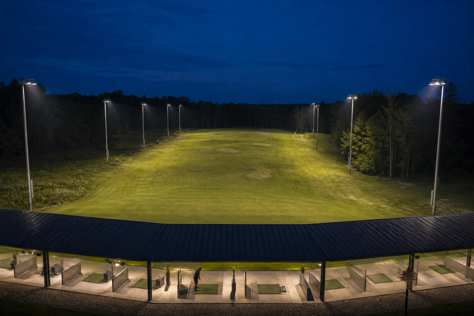
Golf lighting is not simply a larger version of football-field lighting. The player follows a small ball against changing sky, trees and ground backgrounds. A design with high lux on the grass can still fail if the ball disappears in flight or nearby properties receive excessive light.
This guide gives golf operators, contractors and distributors a practical method for planning golf course lighting and driving range lighting without choosing fixtures from wattage alone.
| Project | Primary Visual Task | Main Design Risk |
|---|---|---|
| Driving range | See the ball at impact, in flight and at the landing area | Insufficient vertical light or glare along the player’s view. |
| Practice tee only | Safe setup, swing and short-ball tracking | Player shadows and direct view of luminaires. |
| Night-golf fairway | Follow the shot and walk safely across changing terrain | Dark gaps, uneven transitions and excessive pole intrusion. |
| Green and putting area | Read the ball, cup and surface contours | Hard shadows from a single lighting direction. |
| Paths and service areas | Safe movement without competing with play lighting | Overlighting and adaptation problems. |
A range can be organized around a tee line and distance bands. An entire course is a distributed landscape with multiple playing directions. Treating both as one average-lux calculation produces misleading fixture counts.
Prepare a scaled survey showing the tee line, bay levels, landing area, targets, nets, terrain, buildings, roads and boundaries. Record the direction of play and observer locations. For a multi-level range, include every hitting-deck height because each level sees luminaires differently.
The brief should define operating hours, curfew, horizontal and vertical illuminance, uniformity, color quality, flicker and spill light. It should identify the planning authority and environmental zone. Sport England’s artificial-lighting guidance emphasizes the visual environment and sport-specific requirements rather than one generic level.
| Zone | What to Calculate | Why It Matters |
|---|---|---|
| Tee and first-flight zone | Horizontal and vertical illuminance, shadows and direct glare | The player must see setup, impact and initial ball flight. |
| Mid-flight corridor | Vertical illuminance on planes facing the tee | The ball is viewed in the air, not only on the ground. |
| Landing zones | Horizontal/vertical light and target visibility | Players need to judge distance and locate the ball. |
| Side boundaries | Vertical boundary illuminance and luminaire intensity | Controls light entering adjacent properties and roads. |
| Sky and upper boundary | Upward light and high-angle emission | Limits skyglow and wasted light. |
Lux targets should come from the owner, governing criteria and local approval requirements. The calculation should clearly state whether values are initial or maintained and which maintenance factor is used. A single horizontal grid on the grass is not enough for ball-flight visibility.
Tee-line poles: place luminaires so the golfer is not looking directly into them during address or ball flight. Wide or asymmetric distributions can provide local fill, but the design must check shadows from the player, bay structure and safety screens.
Side poles: arrange poles to create overlapping cross-lighting through the flight and landing zones. Alternating or paired positions may improve uniformity; also check maintenance access, net foundations and drainage.
Far-end lighting: aiming luminaires back toward the tee can create severe direct glare. Use it only when the calculation proves that shielding, mounting and aiming protect all player levels and nearby observers.
Night-golf areas: tees, fairways and greens need separate strategies. Greens benefit from more than one lighting direction to soften shadows. Fairway poles must avoid shot lines, landing areas and maintenance routes. A qualified engineer should verify structural requirements.
Narrow beams reach distant zones but are sensitive to aiming errors. Medium beams overlap adjacent zones. Wider distributions suit near areas but can increase spill at high tilt angles. A robust design combines optics instead of forcing one beam to cover the range.
Mounting height affects aiming, glare, pole loading and maintenance. Higher poles may improve distribution and reduce extreme tilt, but increase structural scope. Review candidate LED golf course lights with model-specific IES files, then test each optic and aiming point.
CIE 150:2017 provides a framework for limiting obtrusive light and emphasizes design-stage control. Because authorities may adopt different limits, record the environmental zone and pre-/post-curfew criteria.
| Acceptance Check | Where to Test | Control Method |
|---|---|---|
| Boundary illuminance | Property lines and sensitive facades | Optics, aiming, shielding and dimming. |
| Luminaire intensity | Views from homes, roads and player positions | Limit high-angle light and direct luminaire visibility. |
| Upward light | Complete installation | Keep beams below useful boundaries and avoid excessive tilt. |
| Curfew operation | Control schedule and lighting scenes | Dim or switch off nonessential zones after operating hours. |
A visor cannot cure poor geometry. Start with pole position and optics, then use shields for critical directions. The sports lighting design guide explains how glare, uniformity and aiming work together.
A range rarely needs every zone at full output. Separate tee bays, targets, landing zones, paths and service areas into control groups. Scheduling and dimming can reduce energy while preserving safe shutdown lighting.
Compare project cost as a complete system:
luminaires, brackets, remote drivers, surge protection and controls;
poles, headframes, foundations, access roads and lifting equipment;
electrical service, panels, trenching, cable, grounding and networking;
survey, photometric design, structural review, permits and environmental studies;
installation, aiming, field measurement, commissioning, training and spares.
Do not compare fixture price without normalizing the included scope. For a systematic quotation review, use the stadium-light manufacturer RFQ checklist and require model-specific photometric and test documents.
Topographic survey, tee levels, landing-area dimensions and terrain model.
Pole-permitted zones, maximum heights, nets and structural restrictions.
Horizontal and vertical targets by distance band or playing zone.
Property boundaries, sensitive observers, roads and environmental zone.
Voltage, controls, operating scenes, curfew and annual operating hours.
Wind, temperature, humidity, corrosion and maintenance-access conditions.
There is no dependable universal quantity. It depends on range length and width, tee levels, targets, poles, mounting height, luminaire output, optics, vertical-light requirements and spill limits.
The golfer observes the ball in the air. Ground-level horizontal lux alone cannot predict whether the ball remains visible through the flight corridor.
Positions are normally developed around the tee line and side boundaries, with cross-lighting toward flight and landing zones. Every position must be checked for player glare, nets, safety, maintenance and neighboring properties.
Usually not efficiently. Near, middle and far zones need different distributions. Combining model-specific optics produces better control than excessive tilt with one beam.
Use correct pole geometry, low high-angle intensity, precise aiming, shielding for critical directions, dimming scenes and a curfew. Verify the result at boundaries and observer locations.
Provide the survey, playing and operating requirements, pole constraints, environmental boundaries, electrical information, controls, approval criteria, delivery terms and commissioning scope.
Send the site plan, tee configuration, landing-zone dimensions, pole restrictions, boundary conditions and operating schedule. Hishine can review the inputs and prepare a model-specific fixture schedule and lighting proposal.
Author 2024-08-06
LED technology itself is not automatically harmful to children’s eyes. This guide explains the differences between permanent eye damage, temporary visual discomfort and sleep disruption, while showing...
Author 2026-07-29
All-in-one and split solar street lights each offer different advantages. This guide compares their system structure, installation, solar panel flexibility, battery capacity, maintenance, cost, and su...